Bridge bearing pad design starts with controlled load transfer
A bridge bearing pad is a structural interface that transfers forces between a bridge superstructure and its supporting substructure while allowing the movement required by temperature, traffic, shrinkage, creep and rotation. Although the component may look simple, its design influences how a bridge responds to daily loading, seasonal temperature changes and long-term deformation. A suitable bearing system must work as part of the complete bridge, not as an isolated rubber component.
For designers and engineers, the central question is not simply whether a bearing can carry a stated vertical reaction. The more useful question is whether the bearing can transfer vertical and horizontal actions, accommodate movement, permit rotation and maintain stable performance without creating unintended restraint. This article explains the main design principles for bridge bearing pads, with emphasis on elastomeric bearings used in bridge construction.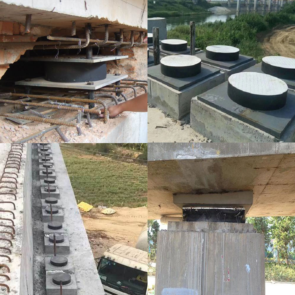
Define the structural actions before selecting the bearing
The first design step is to establish the actions that the bridge bearing must accommodate. These actions normally include permanent load, traffic load, braking or traction effects, wind, seismic effects where relevant, temperature movement, concrete shrinkage, creep and rotation caused by girder deflection. The design should distinguish between actions that must be transferred and movements that must remain free.
Vertical reaction is usually the most visible design input, but it is only one part of the load model. A bearing can experience compression combined with translation and rotation. If these effects are considered separately, the selected bearing may appear adequate in a simplified check while becoming overstressed in service. Engineers should therefore develop load combinations that represent the actual support conditions and should identify the maximum and minimum reactions at every bearing location.
Support geometry also matters. The bearing footprint, contact area, edge distance and stiffness of the supporting concrete influence pressure distribution. Uneven seating, insufficient flatness or local surface damage can concentrate stress at one side of the pad. This can increase bulging, reduce effective contact and introduce rotation that was not included in the original model.
Understand how an elastomeric bearing carries load
An elastomeric bridge bearing is commonly formed from rubber layers, often reinforced with steel plates. The rubber provides flexibility in shear, while the internal reinforcement controls vertical deformation and limits excessive bulging. Under vertical compression, the rubber tends to expand laterally. The bonded reinforcing layers restrain that expansion, allowing the bearing to support substantial vertical force while remaining flexible in horizontal translation.
The relationship between plan area, total rubber thickness, layer thickness and the loaded shape factor affects bearing behavior. A larger loaded area generally lowers average compressive stress, while thinner individual rubber layers can improve control of vertical deformation. At the same time, the bearing must retain enough shear flexibility to accommodate the calculated movement without generating excessive restoring force.
The design should also consider the difference between the total rubber thickness and the overall bearing thickness. Horizontal displacement is mainly accommodated through shear strain in the rubber layers. If the available rubber thickness is too small for the required movement, shear strain can become excessive. If the bearing is too flexible for the support arrangement, movement may become difficult to control. The correct balance depends on the bridge geometry, support spacing and movement demand.
Control translation and rotation at the support
Bridge movement is created by several mechanisms. Temperature changes cause expansion and contraction. Concrete shrinkage and creep alter the effective length and curvature of the superstructure. Traffic loading creates changing rotations at girder ends. Construction tolerances can add initial offsets. A bridge bearing must accommodate the design movement without losing contact or developing harmful restraint.
Elastomeric bearings normally permit translation through shear deformation. Rotation is accommodated through a change in the contact pressure distribution and local deformation of the pad. Designers should check the combined effect of translation and rotation rather than treating them as unrelated movements. A pad that appears acceptable under pure shear may behave differently when one edge is unloaded by end rotation.
Movement direction should be considered in three dimensions. Longitudinal movement may dominate on a straight bridge, but transverse movement can arise from skew, curvature, braking, wind or seismic response. For a skew bridge, the actual movement direction may not align with the longitudinal axis of the deck. The support arrangement should therefore be reviewed using the bridge coordinate system and the real movement vectors.
Where a bridge requires guided or restrained behavior, the guidance mechanism should be designed separately from the elastomeric element. The bearing pad should not be forced to perform a function that belongs to a guide, shear key or restraint system. Clear separation of these functions makes inspection and future maintenance more straightforward.
Design the interface between bearing and concrete
The interface is as important as the pad itself. The top and bottom contact surfaces should be level, clean and capable of providing uniform support. The concrete pedestal should have sufficient strength and dimensional accuracy for the expected reaction. Any grout or leveling arrangement should be compatible with the design intent and should not create a weak or uneven layer beneath the bearing.
The bearing should be positioned so that the effective loaded area remains within the intended support zone under all relevant combinations. Edge proximity can be especially important where rotation is high. If the pad moves toward an edge, part of the bearing may become unsupported, which changes the pressure distribution and may create local damage.
Construction drawings should communicate orientation, center lines, bearing identification, support elevations and any movement direction. A bearing that is installed in the wrong orientation may still look correct from above while producing unexpected restraint during service. Simple markings, clear setting-out information and a recorded installation check can prevent this type of error.
Use standards as a design and verification framework
Standards help engineers define material properties, test methods, tolerances and performance expectations. The selected standard should match the bearing type, bridge jurisdiction and project specification. It is important to distinguish between a material standard, a product standard and a project-specific design requirement.
The ASTM standards portal provides access to standards and technical information used across construction materials, testing and engineering applications. The BSI Knowledge website provides information on British Standards and related technical documents. These sources should be consulted directly by the responsible design team to confirm the current edition and the clauses applicable to the project.
A standard reference does not replace engineering judgment. The design still needs project-specific actions, geometry, environmental exposure and installation requirements. Where a project uses EN, BS, ASTM or another national framework, the calculation basis and acceptance criteria should be stated clearly so that the designer, manufacturer, inspector and contractor are working to the same interpretation.
Check material behavior and environmental exposure
Rubber properties change with temperature, aging, ozone, ultraviolet exposure and contact with chemicals. The selected elastomer should suit the environmental conditions expected at the bridge location. Consideration may be required for cold-weather stiffness, high-temperature behavior, water exposure, salt, industrial contaminants and repeated movement.
Material selection should be supported by documented test data and traceable production controls. Important properties can include hardness, tensile strength, elongation, compression set, ozone resistance and low-temperature flexibility, depending on the applicable standard and project specification. The relevant acceptance limits should be defined before inspection rather than created after a test result is available.
Steel reinforcement also requires attention. Internal plates should be properly bonded, protected and positioned. Inadequate bonding can reduce the intended restraint of lateral rubber expansion. Visible defects, damaged edges, contamination or irregular dimensions should be recorded and assessed against the project criteria.
Verify manufacturing quality before installation
Quality control begins with raw materials and continues through mixing, molding, bonding, trimming and final inspection. A robust inspection plan should identify the required records for rubber compound identification, reinforcement material, mold dimensions, curing conditions and finished bearing measurements.
Dimensional checks should cover plan dimensions, total thickness, individual layer thickness where specified, reinforcement position, flatness and surface condition. Visual inspection should look for cuts, tears, voids, blisters, exposed reinforcement, poor edge trimming and contamination. Testing should be performed according to the chosen standard and should be linked to a clear sampling plan.
Traceability is particularly valuable when multiple bearings are used on one bridge. Marking or identification should allow each bearing to be associated with its manufacturing records, inspection results and installation position. This supports investigation if a movement or alignment issue appears later and helps the project team distinguish between a product issue and an installation issue.
Install the bearing pad without creating unintended restraint
Before installation, the support surface should be checked for elevation, cleanliness, flatness and damage. The bearing should be protected from dragging, twisting and impact. It should be placed at the correct temperature reference position and orientation required by the design documents. Temporary restraints, packing materials and construction debris should not remain in a way that blocks the intended movement.
During girder placement, the load should be introduced in a controlled manner. Sudden impact can damage the bearing or shift it from its intended position. After loading, the exposed edges should be inspected for abnormal bulging, folding, extrusion or uneven contact. The installation record should note the actual position, orientation and any observed deviation.
The surrounding geometry should also be reviewed. Drainage, debris barriers, expansion joints and adjacent concrete details should not interfere with movement. A correctly manufactured bearing can perform poorly if neighboring elements impose an unintended constraint.
Plan inspection around movement and condition
Inspection should focus on condition and behavior rather than appearance alone. Useful observations include pad bulging, shear offset, edge lifting, cracking, splitting, ozone-related surface deterioration, corrosion of exposed components and evidence of contact with foreign materials. The position of the deck relative to the bearing can provide information about movement demand and possible restraint.
Inspection records should include date, temperature where relevant, observed movement direction, photographs, dimensions of visible defects and comparison with previous inspections. Repeated observations are more valuable than isolated descriptions because they show whether a condition is stable, progressing or related to a seasonal cycle.
If unusual deformation is found, the first response should be controlled assessment rather than immediate assumption of product failure. The team should review the original design movement, actual support geometry, adjacent restraints, installation records and environmental conditions. A specialist assessment may be needed where contact loss, severe shear strain or reinforcement exposure is suspected.
Connect the bearing to the complete bridge design
A bridge bearing pad should be selected as part of the bridge movement system. Deck joints, restraints, guides, shear keys, concrete pedestals and drainage details all influence bearing performance. A design review should confirm that the assumed movement at the bearing is compatible with the movement allowed elsewhere in the structure.
The most reliable approach combines structural analysis, material verification, dimensional control, careful installation and planned inspection. No single calculation or visual check can replace the complete sequence. When the bearing function is clearly defined and the interface is controlled, elastomeric bearings can provide a practical and durable method for transferring load while accommodating the movement and rotation inherent in bridge construction.
For technical questions about a bridge bearing pad arrangement, support geometry or inspection finding, use the DLYY contact page to provide the relevant drawings, load cases and site observations for technical review.
Frequently asked questions
1. What is the primary function of a bridge bearing pad?
Its primary function is to transfer vertical and horizontal actions between the bridge superstructure and substructure while accommodating the movement and rotation allowed by the design. The bearing should support the structure without introducing unintended restraint.
2. How does an elastomeric bearing accommodate horizontal movement?
It normally accommodates horizontal movement through shear deformation of the rubber layers. The required rubber thickness, movement demand and shear strain must be considered together so that the bearing remains stable and within the applicable design limits.
3. Why are internal steel plates used in a rubber bearing?
Internal steel plates restrain lateral expansion of the rubber under compression. This increases the bearing's vertical load-carrying capability and helps control deformation while the rubber remains flexible in shear.
4. What should be checked before installing a bearing pad?
The support surface, elevation, flatness, cleanliness, bearing orientation, center position and movement direction should be checked. The bearing should also be free from visible damage, contamination and distortion before the bridge load is applied.
5. Which defects require closer engineering assessment?
Significant edge lifting, loss of contact, severe shear offset, deep cracking, splitting, exposed reinforcement, abnormal bulging or evidence of restraint should receive closer assessment. The review should consider design actions, installation records and surrounding structural details.
6. How can inspection records improve bridge bearing maintenance?
Consistent records create a baseline for comparison. Dates, temperatures, movement observations, photographs and measured defect changes help the inspection team identify progression, seasonal behavior and possible interaction with adjacent bridge components.

 Water-Filled Rubber Dam: 5 Field Failures That Show Up Before the Dam Bag Bursts
 Bridge Bearing Pad Inspection and Maintenance: A Field Guide for Safer Bridge Construction
 Bridge Bearing Pad Design: Load Transfer, Movement and Service Reliability
