Real failure cases and specification lessons for Bridge Bearing Pad procurement. Ozone cracking, shim corrosion, bond separation, and shape factor mistakes that shorten service life.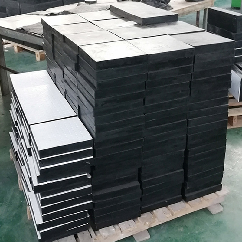
The Difference Between Five Years and Fifty Years
Two bridges. Same span. Same climate. Same traffic volume. One set of Bridge Bearing Pad units gets replaced after five years, with abutment repairs that cost triple the original bearing price. The other set passes a 20-year inspection with no findings.
The difference is not luck. It comes down to four specific decisions made during procurement: rubber compound selection, steel shim protection, bond quality verification, and shape factor calculation. Get those right and the bearing outlasts the deck overlay. Get them wrong and you are jacking the bridge before the first major maintenance cycle.Failure Mode 1: Ozone CrackingOzone exists in ambient air at 0.01 to 0.10 parts per million. Urban areas with heavy traffic run higher. Ozone attacks unsaturated rubber molecules, breaking polymer chains and producing surface cracks perpendicular to the stress direction.What happens:
Natural rubber without antiozonant protection develops visible cracks within two to four years outdoors.
Cracks start at the surface and grow deeper under cyclic traffic loading.
Once cracks reach the steel shim, moisture follows and corrosion begins.
Real case:
A municipal overpass in a coastal city specified natural rubber pads without wax or chemical antiozonant. At 54 months, surface cracks reached 3 mm depth on the south-facing side of every bearing. Two pads had exposed shims. Replacement cost, including jacking and temporary shoring, ran four times the original bearing contract.
What prevents it:
Specify chloroprene (neoprene) for any outdoor installation. Its chlorine-modified polymer structure resists ozone inherently.
If natural rubber is required for low-temperature flexibility, mandate a wax bloom antiozonant at minimum 2 parts per hundred rubber and verify via ASTM D1149 ozone chamber testing.
For Grade 3 or Grade 5 per ASTM D4014, ozone resistance is a mandatory qualification test. Do not waive it.
Failure Mode 2: Steel Shim Corrosion
Internal steel shims are fully encapsulated in rubber during vulcanization. If the encapsulation is incomplete due to poor mold design, inadequate rubber flow, or handling damage, moisture reaches the shim edge.
Corrosion mechanism:
Rust occupies six to eight times the volume of the original steel.
Expanding rust pushes against the surrounding rubber, causing blisters and delamination.
The rubber-to-steel bond fails progressively from the edge inward.
Load capacity drops as the effective bonded area shrinks.Real case:
A highway bridge in a freeze-thaw region received pads with ungalvanized steel shims. The manufacturer relied solely on rubber encapsulation for corrosion protection. At eight years, 12 of 48 bearings showed edge blisters. Sectioning revealed rust penetration 15 mm from the edge. The entire bearing set was replaced at year ten.
What prevents it:
Specify galvanized steel shims per ASTM A123 for any pad exposed to outdoor conditions, coastal air, or deicing salt.
Require minimum rubber cover over shim edges: 5 mm for internal shims, 8 mm for external cover layers.
Request cross-section photos from the manufacturer showing shim edge encapsulation before approving production.
Failure Mode 3: Bond Separation Between Rubber and Shim
The bond between elastomer and steel forms during vulcanization under heat and pressure. Bond strength depends on three things: surface preparation of the steel (grit blasting or chemical etching), the adhesive system used (typically silane or phenolic-based primer plus cover coat), and the cure temperature and time.
Bond failure indicators:
Visible gap between rubber and shim at the pad edge
Audible clicking or popping during girder placement
Progressive separation under repeated loading
Acceptance criteria:Per ASTM D4014, peel strength between rubber and steel must be minimum 10 kN/m when tested at 25 mm/min crosshead speed. Quality manufacturers target 15 kN/m or higher.Real case:A precast concrete girder bridge in Southeast Asia used pads from a supplier that skipped the adhesive primer step to reduce cost. Within 18 months, 8 of 96 bearings showed edge separation. Lab testing confirmed peel strength below 3 kN/m. The full set was replaced under warranty, but the cost of site jacking and traffic management exceeded the original pad contract.
What prevents it:
Require peel test certificates for each production batch.
Conduct independent bond testing on random samples from incoming shipments.
Verify the manufacturer's adhesive system is rated for the specified rubber compound and cure cycle.Failure Mode 4: Underspecified Shape FactorShape factor is the ratio of loaded area to perimeter-free area of a single rubber layer. It controls vertical stiffness and load capacity.Consequences of low shape factor:
Excessive vertical deflection under load
Edge bulging beyond acceptable limits
Accelerated rubber fatigue at the bulging zone
Potential rollover instability in high-compression applications
Design rule:
For highway bridge bearings, minimum shape factor S = 4 per AASHTO M251. For heavily loaded girders, S = 6 to 8 is recommended. Each rubber layer thickness should be calculated based on the required vertical stiffness, not chosen arbitrarily.
Real case:
A railway bridge designer specified 12 mm rubber layers to reduce total bearing height. The resulting shape factor was S = 3.2. Within three years, the bearings showed 15% compression set and visible edge rollover. Replacement bearings with 8 mm layers and S = 5.8 performed without issue for over 15 years.
What prevents it:
Calculate shape factor for each proposed pad configuration before ordering.
Specify maximum rubber layer thickness as a function of plan dimensions.
Request the manufacturer's shape factor calculation in the submittal package.Failure Mode 5: Improper InstallationA correctly manufactured pad fails early if installation conditions are wrong.Common installation errors:
Sole plate not level, creating a gap larger than 0.5 mm between pad and girder
Pad positioned off-center, causing eccentric loading
Pad twisted during placement, introducing pre-compression
Ambient temperature at installation ignored, leading to incorrect shim offset for thermal movement
Real case:
A curved steel box girder bridge in Europe had bearings installed during winter at -5°C. The installer did not adjust the shim position for the temperature offset. When summer temperatures reached +35°C, thermal expansion pushed the girder beyond the bearing's movement capacity. The pad sheared at the bond line. Replacement cost exceeded €40,000 per bearing location.
What prevents it:
Specify installation temperature range in the contract documents.
Require installer certification or manufacturer-supervised installation for critical bridges.
Mandate post-installation inspection including feeler gauge check of pad-to-girder contact.
Summary: What to Check Before You Order
| Failure Mode |
Root Cause |
Specification Fix |
How to Verify |
| Ozone cracking |
Natural rubber without protection |
Specify neoprene or NR with antiozonant |
ASTM D1149 ozone chamber test |
| Shim corrosion |
Ungalvanized steel, thin rubber cover |
Galvanized shims, 5 mm minimum cover |
Cross-section photo, mill certificate |
| Bond separation |
Missing adhesive, poor cure |
Peel test at 10 kN/m minimum |
Batch peel test certificate |
| Low shape factor |
Rubber layers too thick |
Calculate S ≥ 4, prefer S ≥ 6 |
Manufacturer submittal with calculation |
| Installation error |
Temperature offset, misalignment |
Certified installer, post-install inspection |
Feeler gauge, alignment survey |
What to SpecA Bridge Bearing Pad that lasts 50 years is not expensive because of the rubber. It is specified correctly: chloroprene compound with verified ozone resistance, galvanized shims with adequate rubber cover, bond strength proven by peel test, shape factor calculated for the actual load, and installation supervised by qualified personnel. Every premature failure in the cases above traces back to one missing specification clause. Adding that clause costs nothing. Omitting it costs a bridge closure.

 How Much Load Can a Bridge Bearing Pad Actually Carry? Engineering Data for Safe Girder Support
 Is Your Bridge Bearing Pad Specified for the Wrong Rubber Grade? Why Elastomeric Bridge Bearing Pad Selection Decides 50-Year Deck Life
 Can a Loading Dock Bumper Survive -30°C Winters and +50°C Summers? Here Is the Extreme-Weather Data
 Are Your Dock Bumpers Specified for the Wrong Impact Profile? Why a Loading Dock Bumper with a Steel Face Outperforms in Real Traffic